- Home
- › Products
- › Cryogenic
- › Actuated Valves
CRYOGENIC
Type 01643 - Actuated Globe Valve
|
Cryogenic-Globe Valves with Pneumatic Actuator, PN50 (DN150=PN40) “Fire safe” type test approval acc. to EN ISO 10497 Stainless steel body and topwork Actuator - air opens, spring closes or contrary "live loaded" gland packing "cleaned and degreased for oxygen service" - the standard actuator is not cleaned and degreased for oxygen Part No. 01643.X.0010 possible connections: - Butt weld connection for stainless steel pipes acc. to ISO 1127 or ASTM A312 - Socket weld connection for stainless steel pipes acc. to ISO 1127 or ASTM A312 - Female thread connection (G) acc. to ISO 228/1 or NPT acc. to ANSI B 1.20.1 Please specify the required connection when ordering! Available options - on request only: - Solenoid valves - Electropneumatic positioner - Inductive Proximity Switches - Position and Limit Switches - Air control sets - Electric actuator - Welded stainless steel stubs acc. to ISO 1127 or ASTM A312 - length FF + 200mm - Actuator "cleaned and degreased for oxygen service" - Further pipe wall thicknesses - Valve with check disc - valve with control disc (tapered design) Applications: Approved for air gases, vapours and cryogenic liquefied gases incl. LNG. Working temperature: -196°C / -321°F (77K) up to +120°C / +248°F (393K) |
|
||||||||||||||||||||||||||||||||||||||||||||||||||||||||||||||
|
|
||||||||||||||||||||||||||||||||||||||||||||||||||||||||||||||


| Type 01643 - Standard design | Technical Data | |||||||||||
| Nominal size | DN | 10 | 15 | 20 | 25 | 32 | 40 | 50 | 65 | 80 | 100 | 150 |
| Dimension code | .X. | 0100 | 0150 | 0200 | 0250 | 0320 | 0400 | 0500 | 0650 | 0800 | 1000 | 1500 |
| Face-to-face dimension | FF | 70 | 85 | 100 | 115 | 115 | 130 | 155 | 205 | 245 | 280 | 400 |
| Height | H | 370 | 370 | 370 | 375 | 405 | 420 | 425 | 510 | 575 | 635 | 685 |
| Length | E | 195 | 195 | 200 | 200 | 230 | 230 | 235 | 300 | 300 | 300 | 350 |
| Actuator-Ø | M | dependent on actuator | ||||||||||
| Wrench size across flats | S2 | 30 | 30 | 30 | 30 | 36 | 36 | 36 | 36 | 36 | 41 | 41 |
| Weight w/o actuator | ca. kg | 1.9 | 2.15 | 2.4 | 3.1 | 3.8 | 6.5 | 9.0 | 15.2 | 20.0 | 28.0 | 60.9 |
| Stroke | mm | 10 | 10 | 7 | 9 | 9 | 11 | 15 | 23 | 23 | 30 | 40 |
| Dimensions in mm. Compliance of tightness requirements acc. to EN 1626 for DN150 up to 20 bar differential pressure. In the range of >20-40 bar, 350-700ml per second (1 bar, 20°C [68°F]) are reached. * These figures refer to measurements for the flow direction. |
|
Connection types |
|
Butt weld connection acc. to · ISO 1127 |
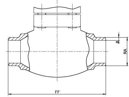 |
| DN | Face-to-face dim. (FF) [mm] | Outside pipe-Ø ISO (RA) [mm] | Wall thickness pipe ISO (a) [mm] | *Kvs-value [m³/h] | *Cv-value [gal/min] | **Weight w.a. [kg] | Order reference |
| 10 | 70 | 13.5 | 1.0 | 1.6 | 1.9 | 1.9 | BW 13.5x1.0 |
| 15 | 85 | 17.2 | 1.6 | 3.8 | 4.4 | 2.2 | BW 17.2x1.6 |
| 15 | 85 | 21.3 | 2.0 | 4.3 | 5.0 | 2.2 | BW 21.3x2.0 |
| 20 | 100 | 26.9 | 2.0 | 6.7 | 7.8 | 2.4 | BW 26.9x2.0 |
| 25 | 115 | 33.7 | 2.0 | 11.5 | 13.4 | 3.1 | BW 33.7x2.0 |
| 32 | 115 | 38.0 | 2.0 | 14.0 | 16.2 | 3.8 | BW 38.0x2.0 |
| 40 | 130 | 42.4 | 2.0 | 20.6 | 23.9 | 6.5 | BW 42.4x2.0 |
| 40 | 130 | 48.3 | 2.0 | 22.6 | 26.3 | 6.5 | BW 48.3x2.0 |
| 50 | 155 | 60.3 | 2.0 | 37.1 | 43.2 | 9.0 | BW 60.3x2.0 |
| 65 | 205 | 76.1 | 2.6 | 71.1 | 82.9 | 15.2 | BW 76.1x2.6 |
| 80 | 245 | 88.9 | 3.2 | 104.0 | 121.3 | 20.0 | BW 88.9x3.2 |
| 100 | 280 | 114.3 | 6.0 | 170.0 | 198.3 | 28.0 | BW 114.3x6.0 |
| 150 | 400 | 168.3 | 7.1 | 350.0 | 408.4 | 60.9 | BW 168.3x7.1 |
|
Butt weld connection acc. to · ASTM A312 |
|
S10 S40 |
| DN | Face-to-face dim. (FF) [mm] | Outside pipe-Ø ASTM (RA) [inch / mm] | Wall thickness pipe ASTM (a) [mm] | *Kvs-value [m³/h] | *Cv-value [gal/min] | **Weight w.a. [kg] | Order reference |
| 10 | 70 | 1/4" / 13.72 | 1.65 | 1.6 | 1.9 | 1.9 | BW 13.72x1.65 |
| 15 | 85 | 1/2" / 17.15 | 1.65 | 3.8 | 4.4 | 2.2 | BW 17.15x1.65 |
| 15 | 85 | 1/2" / 21.34 | 2.11 | 4.3 | 5.0 | 2.2 | BW 21.34x2.11 |
| 20 | 100 | 3/4" / 26.67 | 2.11 | 6.7 | 7.8 | 2.4 | BW 26.67x2.11 |
| 25 | 115 | 1" / 33.40 | 2.77 | 11.5 | 13.4 | 3.1 | BW 33.40x2.77 |
| 40 | 130 | 1-1/2" / 42.16 | 2.77 | 20.6 | 23.9 | 6.5 | BW 42.16x2.77 |
| 40 | 130 | 1-1/2" / 48.26 | 2.77 | 22.6 | 26.3 | 6.5 | BW 48.26x2.77 |
| 50 | 155 | 2" / 60.32 | 2.77 | 37.1 | 43.2 | 9.0 | BW 60.32x2.77 |
| 65 | 205 | 2-1/2" / 73.02 | 3.05 | 71.1 | 82.9 | 15.2 | BW 73.02x3.05 |
| 80 | 245 | 3" / 88.90 | 3.05 | 104.0 | 121.3 | 20.0 | BW 88.90x3.05 |
| 100 | 280 | 4" / 114.30 | 3.05 | 170.0 | 198.3 | 28.0 | BW 114.30x3.05 |
| 150 | 400 | 6" / 168.27 | 3.40 | 350.0 | 408.4 | 60.9 | BW 168.27x3.40 |
| 10 | 70 | 1/4" / 13.72 | 2.24 | 1.6 | 1.9 | 1.9 | BW 13.72x2.24 |
| 15 | 85 | 1/2" / 17.15 | 2.31 | 3.8 | 4.4 | 2.2 | BW 17.15x2.31 |
| 15 | 85 | 1/2" / 21.34 | 2.77 | 4.3 | 5.0 | 2.2 | BW 21.34x2.77 |
| 20 | 100 | 3/4" / 26.67 | 2.87 | 6.7 | 7.8 | 2.4 | BW 26.67x2.87 |
| 25 | 115 | 1" / 33.40 | 3.38 | 11.5 | 13.4 | 3.1 | BW 33.40x3.38 |
| 40 | 130 | 1-1/2" / 42.16 | 3.56 | 20.6 | 23.9 | 6.5 | BW 42.16x3.56 |
| 40 | 130 | 1-1/2" / 48.26 | 3.68 | 22.6 | 26.3 | 6.5 | BW 48.26x3.68 |
| 50 | 155 | 2" / 60.32 | 3.91 | 37.1 | 43.2 | 9.0 | BW 60.32x3.91 |
| 65 | 205 | 2-1/2" / 73.02 | 5.16 | 71.1 | 82.9 | 15.2 | BW 73.02x5.16 |
| 80 | 245 | 3" / 88.90 | 5.49 | 104.0 | 121.3 | 20.0 | BW 88.90x5.49 |
| 100 | 280 | 4" / 114.30 | 6.02 | 170.0 | 198.3 | 28.0 | BW 114.30x6.02 |
| 150 | 400 | 6" / 168.27 | 7.11 | 350.0 | 408.4 | 60.9 | BW 168.27x7.11 |
|
* These figures refer to measurements for the flow direction. ** w.a. = without actuator |
|
Connection types |
|
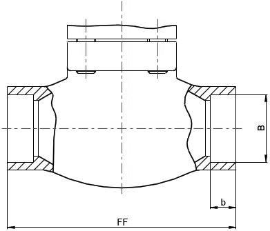
Socket weld connection acc. to · ISO 1127 · ASTM A312 |
| DN | Face-to-face dim. (FF) [mm] | Socket depth (b) [mm] | Socket diameter (B) [mm] | *Kvs-value [m³/h] | *Cv-value [gal/min] | **Weight, w.a. [kg] | order reference [ØISO / ØASTM] |
| 10 | 70 | 6 | 14.1 | 1.6 | 1.9 | 1.9 | SW 13.5 / 13.72 |
| 15 | 85 | 10 | 17.5 | 3.8 | 4.4 | 2.2 | SW 17.2 / 17.15 |
| 15 | 85 | 10 | 21.5 | 4.3 | 5.0 | 2.2 | SW 21.3 / 21.34 |
| 20 | 100 | 13 | 27.5 | 6.7 | 7.8 | 2.4 | SW 26.9 / 26.67 |
| 25 | 115 | 13 | 34.1 | 11.5 | 13.4 | 3.1 | SW 33.7 / 33.4 |
| 40 | 130 | 13 | 42.8 | 20.6 | 23.9 | 6.5 | SW 42.4 / 42.16 |
| 40 | 130 | 13 | 48.6 | 22.6 | 26.3 | 6.5 | SW 48.3 / 48.26 |
| 50 | 155 | 16 | 61.1 | 37.1 | 43.2 | 9.0 | SW 60.3 / 60.32 |
| 65 | 205 | 16 | 74.0 | 71.1 | 82.9 | 15.1 | SW 73.02 |
| 65 | 205 | 16 | 76.8 | 71.1 | 82.9 | 15.2 | SW 76.1 |
| 80 | 245 | 16 | 90.0 | 104.0 | 121.3 | 20.0 | SW 88.9 |
| 100 | 280 | 20 | 114.8 | 170.0 | 198.3 | 28.0 | SW 114.3 |
| 150 | 400 | 20 | 168.2 | 350.0 | 408.4 | 60.9 | SW 168.3 / 168.27 |
 |
|
Female thread connection acc. to · ISO 228/1 (G) · NPT acc. to ANSI B 1.20.1 (NPT) |
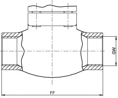 |
| DN | Face-to-face dim. (FF) [mm] | Thread size (GW) | *Kvs-value [m³/h] | *Cv-value [gal/min] | **Weight, w.a. [kg] | order reference G-Thread | order reference NPT-Thread |
| 10 | 70 | 1/4'' | 1.6 | 1.9 | 1.9 | 1/4 BSPP | 1/4" NPT |
| 10 | 70 | 3/8'' | 2.2 | 2.6 | 1.9 | 3/8 BSPP | 3/8" NPT |
| 15 | 85 | 1/2'' | 4.3 | 5.0 | 2.2 | 1/2 BSPP | 1/2" NPT |
| 20 | 100 | 3/4'' | 6.7 | 7.8 | 2.4 | 3/4 BSPP | 3/4" NPT |
| 25 | 115 | 1'' | 11.5 | 13.4 | 3.1 | 1 BSPP | 1" NPT |
| 40 | 130 | 1-1/4'' | 20.6 | 23.9 | 6.5 | 1-1/4 BSPP | 1-1/4" NPT |
| 40 | 130 | 1-1/2'' | 22.6 | 26.3 | 6.5 | 1-1/2 BSPP | 1-1/2" NPT |
| 50 | 155 | 2'' | 37.1 | 43.2 | 9.0 | 2 BSPP | 2" NPT |
|
* These figures refer to measurements for the flow direction. ** w.a. = withour actuator |


